Week #4 Our first working circuits using surface mount components.
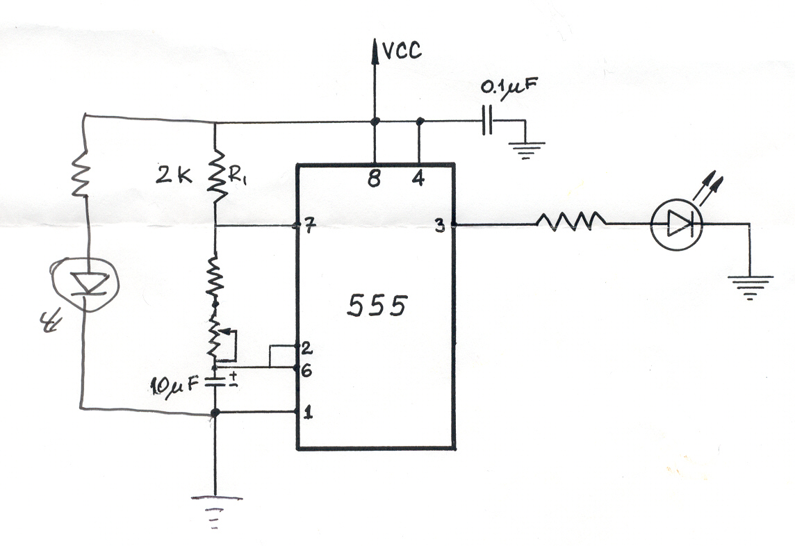
The following page shows a transformation from drawing a circuit out on paper, transferring to board, and soldering on surface mount components. The circuit is 1 steady LED and one variable flashing LED.
|
|
|
Devlopment stages of circuit.
The circuit must be drawn out on paper first. From here it will be transferred to a circuit board ready for components. |
|
|
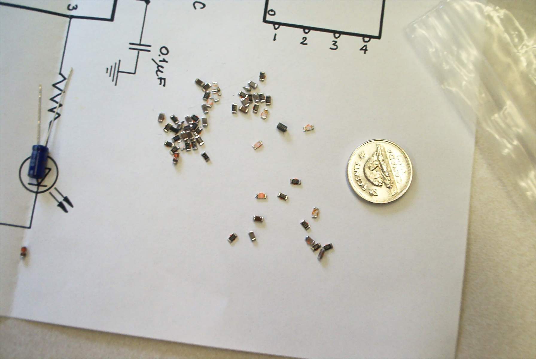
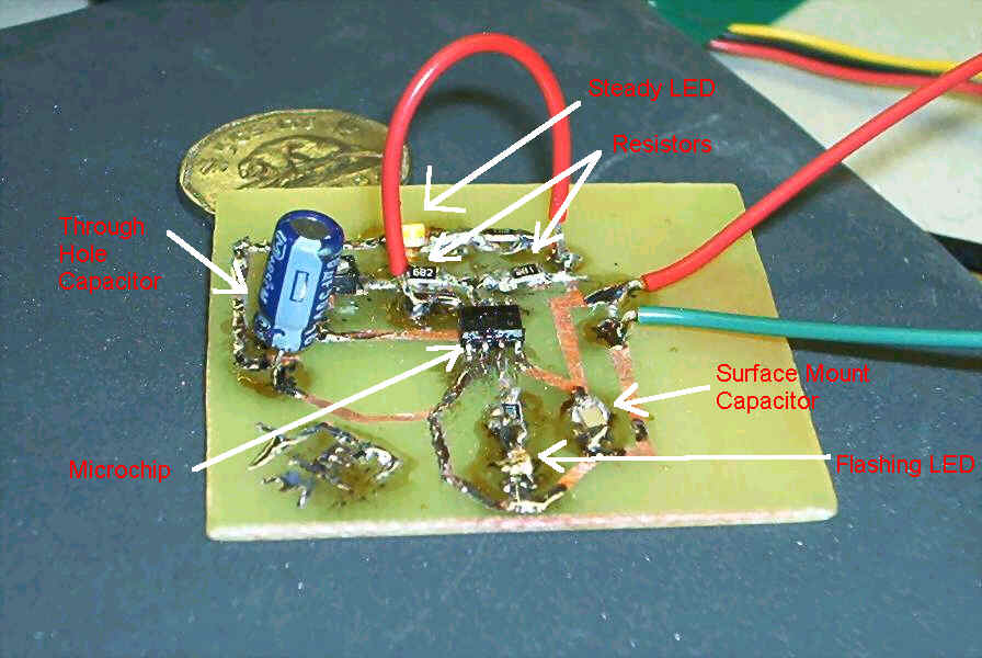
Surface mount components
Note the size of the surface mount components compared to the coin as reference.
|
|
|
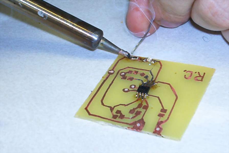
Mounting and soldering of components.
Components are mounted using an everyday soldering iron. Notice the fine craftsmanship here!! |
|
|
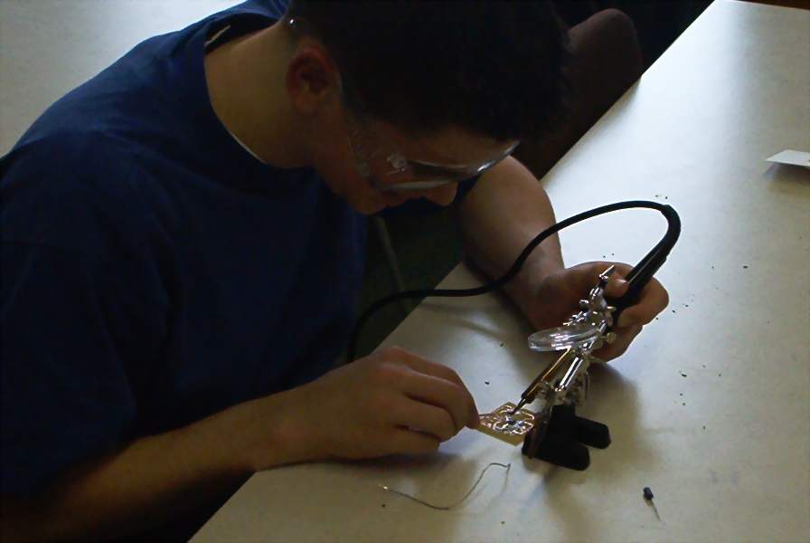
Soldering process.
In some cases a magnifying glass needs to be used because the parts are so small.
|
|
|
Finished circuit board
Note the size comparison between the surface mount capacitor and the through hole capacitor. |
|
|
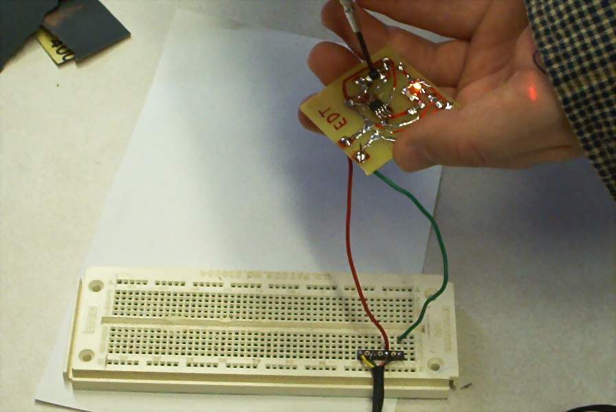
Testing Circuit
Circuits are hooked to a power supply and the speed of the flashing LED can be changed.
|
|
|
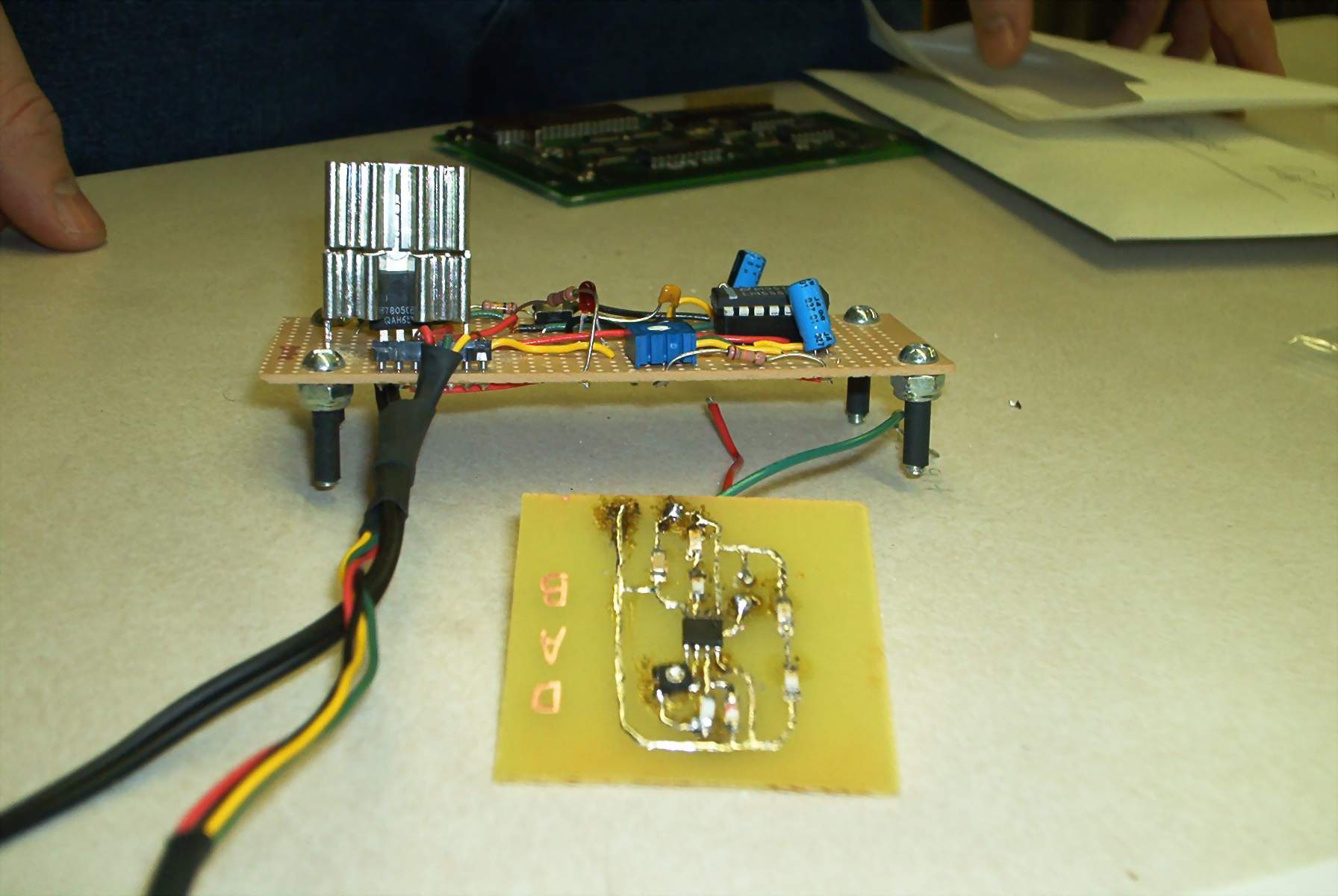
Size comparison
These two circuits do basically the same thing. Note the size difference between the surface mount in front and the through hole in the background. |