Meeting Updates will be posted here.
|
|
|
Meeting No.: 1 Date: 17 Jan 02
Purpose: Introduction into the design objectives
Minutes: - Soldering explanation - through vs. surface mount
- Methods of etching circuit boards - marker and chemicals vs. photo detective
- Design of a circuit board
Problems - It could take a lot of time to get the proper training to do surface mounting
- A very good experience if we could try a surface mount
- Do we have the proper equipment to do a surface mount?
- We do not see a problem with marker and chemical or the photo detective approach for etching the cct boards
- Should we use one cct board of a multiple?
- One chassis of a multiple?
Solutions: No solutions as of yet, we are still brainstorming
Results: Individual roles and responsibilities are stating to develop, after the next meeting the project should start to come together.
|
Meeting No.: 2 Date: 24 Jan. 2002
Purpose: Gain Practical experience in soldering, circuit board layout and etching boards
Minutes: - Chassis design and circuit board mounting was discussed sketches to be reviewed at next weeks meeting
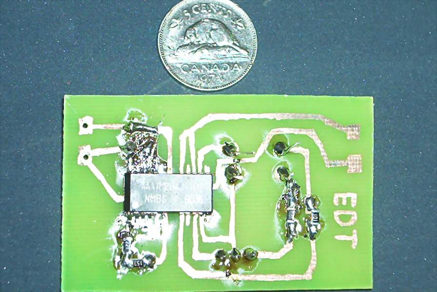
- Practice circuit board were etched, drilled for through hole mounting and components were then surfaced mounted and through hole mounted
- The components mounted were:
2 capacitors
2 though hole resistors
1 transistor
4 surface mounted resistors
1 IC chip
Problems: - The ferric chloride that we used took a long time to etch the boards
- We did not have enough permanent markers; therefore it took along time for everyone to design their circuit board.
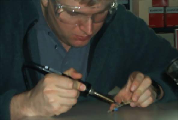
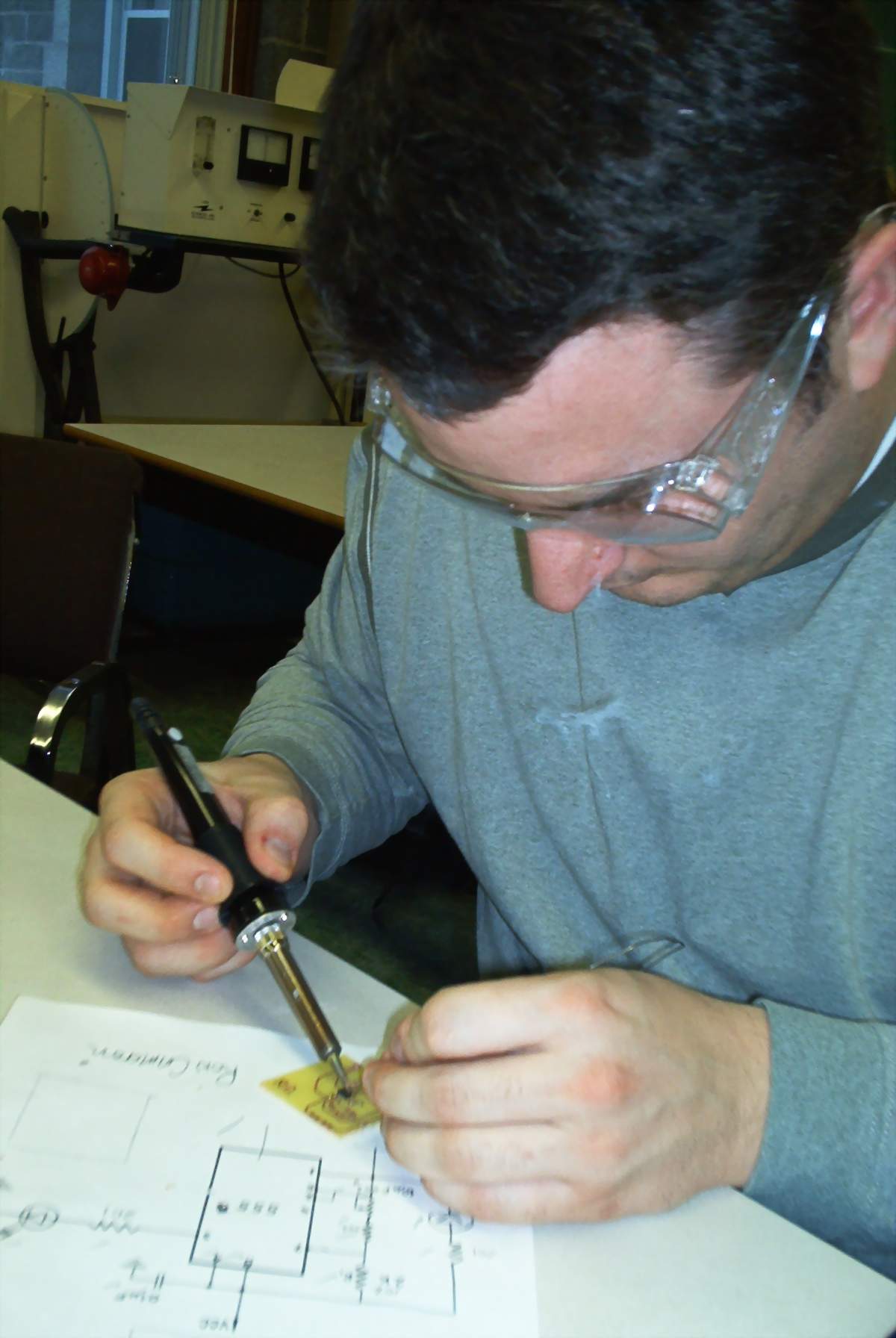
- There were only four soldering kits; therefore once again it took a long time for everyone to get their practical experience.
Solutions: - get more supplies so at least half the group can be working at one time. i.e. 2 more soldering work stations and more permanent markers (red and green seem to work the best)
- It is possible that heating up the ferric chloride will improve the reaction time
Results: Everyone finished their circuit board etched but not everyone got their components mounted on their circuit board do to the lack of supplies and the ferric chloride was slow
|
|
|
|
Meeting No.: 3 Date: 01 Feb. 2002
Purpose: Gain more practical experience designing circuit boards and soldering
Minutes: - Finished our practice circuit boards
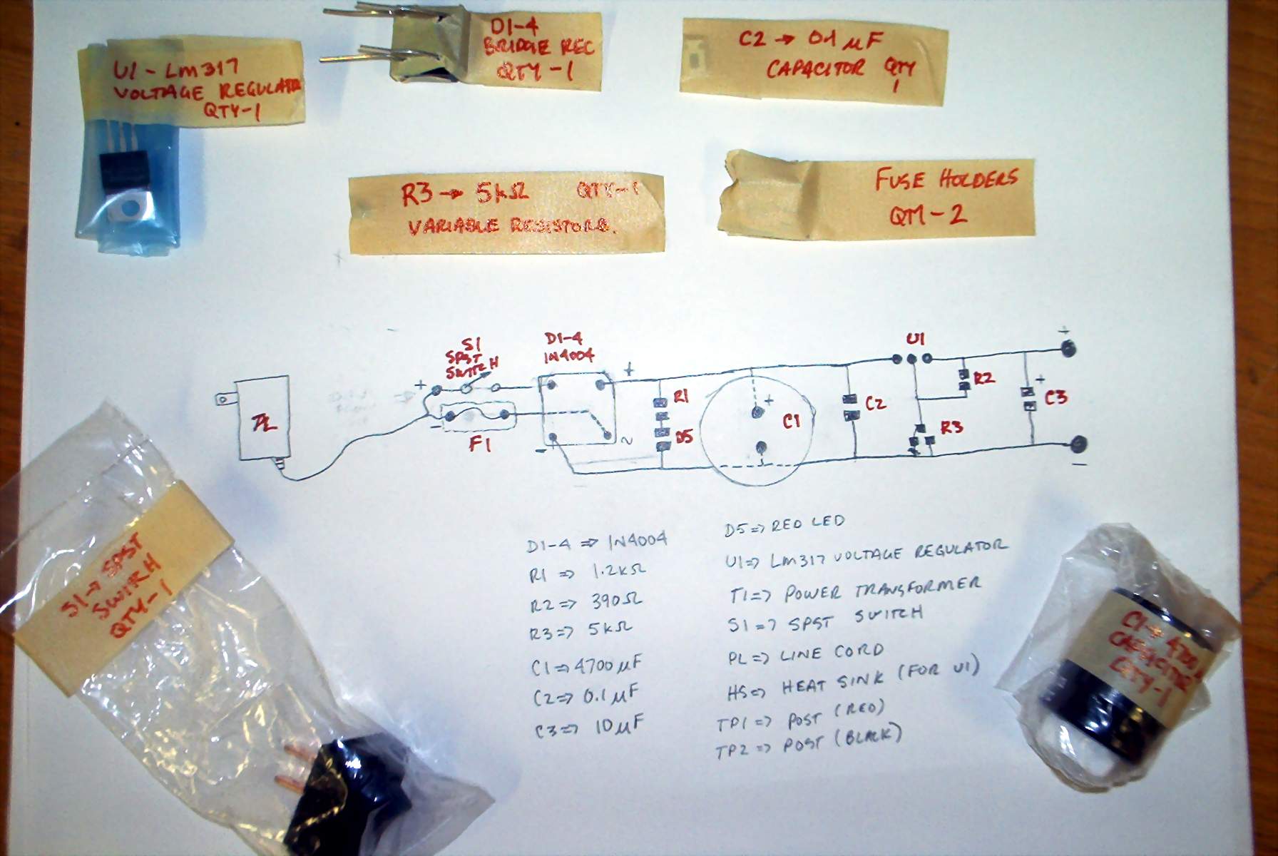
- Group received parts for our project; an inventory was taken and all parts received
- Design a circuit board for L.E.D. display
- All parts required to construct the L.E.D. circuit were distributed
Problems: - the design of the L.E.D. circuit was not done to scale
- Very difficult to see surface mounted components
- Not enough soldering irons
- The thermo probe is limited to lab use
Solutions:- insure next circuit board design is done to scale
- See about the purchasing of magnifying glasses for soldering and soldering irons
- Discuss with the group the possibility of designing a battery operated thermo conductivity probe
Results : Some great sketches of a possible chassis design were received, once we get some more insight into the actual dimensions of the individual circuit boards we will be able to finalize the design.
|
Meeting No.: 4 Date: 7 Feb 02
Purpose: Finish design and construction of flashing LED cct board.
Minutes: - Finished the design of the
flashing LED board, and initiated
construction.
- Unofficial brainstorm re: webpage.
Problems: - Long waits during lab, time was
used inefficiently,
Solutions: - Ensure more organization in the
future.
Results : Approximately two thirds of the class
have produced working circuit boards.
There seems to be more pride involved
this time, as the result actually
performs a task.
|
|
|
|
Meeting No.: 5 Date: 14 Feb 02
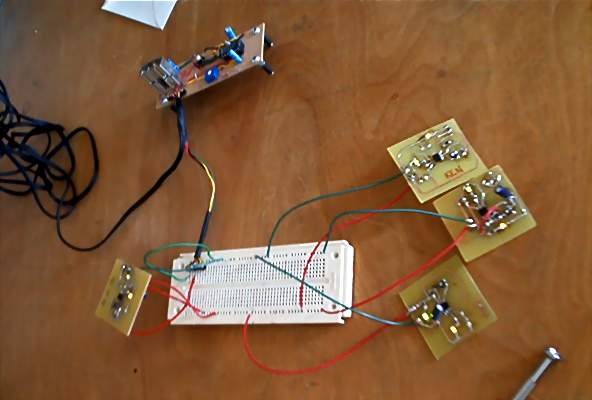
Purpose: Finish the blinking LED circuit; muster the parts for individual circuit boards. (Thermo conductivity probe) and to start the design of the probe layout.
Minutes: - finished our blinking LED circuit
boards(Trouble shooting circuit connections)
- Groups began on their portions of the
thermo probe (drawings)
- Main parts were given to each
group for circuit drawings
- Downloaded part information
on the Internet
Problems: - some circuits (practice LED) were
not working; LED’s were not blinking
- Need better storage for parts
from individual circuits boards
- People from other labs were interrupting
and disturbing our lab while soldering was
being preformed or instruction was given
out.
Solutions: - It was found that some of the
capacitors were U/S, which was causing
the LED to malfunction.
- The interruption problem was brought up
with Professor Tarnawski
Results: - Most of the LED’s are complete and
those that are not will be next meeting
- Most parts have been mustered and
categorized.
|
Meeting No. 6 Date: 28 Feb 02
Purpose: To continue designing circuit board prototypes
Minutes: -Finish Prototype board design
-Start AutoCAD drawings for circuits
-Transplant AutoCAD drawings to group Printed Circuit Board (PCB)
-Make group PCB and populate with parts
Problems: -Lab instructor (Jeff), is spread to thin
- No circuit diagram for digital display
- Lack of Proper tools
- Instructions are quite vague
Solutions: - Start each lab period with a meeting including lab instructor to find
out what is expected objectives of each lab and to find out what parts
or documentation is missing
Results: - everyone was able to get their blinking LED circuit to work
- Most groups are getting a good start on Prototypes
|
|
|
|
Meeting No. 7 Date: 7 Mar 02
Purpose:To have the prototype of the Thermo
Conductivity Probe completed
Minutes:-the large Probe was constructed and
resistance check were carried out on
the heater cable and the thermo coupler
- The variable Power supply is close to
completion
- The 15v power supply is near completion
- The boards for the change in temperature
indicator/control unit, the
heater/thermocouple, and the amplifier are
all etched and ready for assembly
-The T display board is designed and will
be etched next week
Problems:-once again the lab assistant is being
over occupied
- Some tools requested are ‘C’ clamps and
jig saw for cutting cct boards
- Locating serviceable part for the T
display
- It may have been an unreasonable goal to
think that the prototype would
be complete this week
Solutions:-if all the requested part is available
the prototype should be completed for
next week
-If this project is to be undertaken next
year again the a better inventory of
the tools should be consider at the
beginning
- Set more reasonable weekly goals
- Consider a lab assistant just for the
thermocouple
Results: The individual cct are coming together and
a working prototype and a
working final project are foreseeable
|